Distortion approximately 5 under full load conditions.
Cvt stabilizer circuit diagram.
If the unit is correctly installed with a protecting fuse or circuit breaker then the cvt will blow the fuse breaker before damaging energy gets to the electronic equipment being protected.
In this circuit there are small changing from the first circuit.
Use 500ma to 1 a transformer.
Here is another simple circuit of autocut for manual stabilizer.
Tap voltage approximately 5 12 kv depending on the type is taken from the lowest capacitor section and fed to an electromagnetic circuit in the cast aluminum base box.
Voltage stabilizer repairक य आपक voltage stabilizer भ high voltage द त ह त य video ज र र द ख duration.
The cvt has a magnetic circuit which becomes a very low impedance when fed with high voltage.
A 5v dc input is used to power the microcontroller.
The presets p1 to p7 can be modified as per the needed tripping points which is able to correspond to the output ssr switching and the successive transformer tap.
You can also check this circuit by connecting with 0 12 transformer with 12v relay.
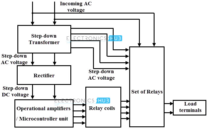
The suggested circuit of a basic 5 kva to 10 kva automatic voltage stabilizer circuit is simple to recognize.
The input voltage ranges 170 to 260 v and output regulation is 230 2 at no load to full load.
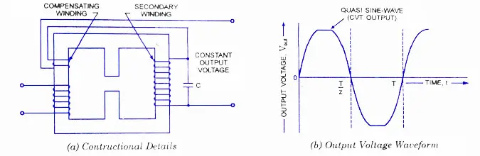
It has no moving parts.
The primary is on the side of a magnetic shunt ad the secondary is on the opposite side with a tuned coil circuit.
Automatic voltage stabilizer circuit diagram 2.
A cvt consists of a high voltage resonant winding and a capacitor that produces a regulated output voltage for any type of input varying current.
The voltage regulation possible in a cvt also is good.
All the opamps are organized in regular voltage comparator modes.
Automatic voltage stabilizer circuit diagram voltage stabilizer circuit operation.
A practical circuit of a cvt power supply is given in figure.
Typical schematic diagram of a cvt the main applications of cvt in high voltage networks above 36 kv are given below.
If you use 12 0 12 transformer then use 24v relay.
A special transformer with resonant tank circuit formed by resonant winding and capacitor keeps output voltage constant.
This is required because there is no internal crystal present in pic 16f873a.
Rating of 50 150 250 350 500 750 1000 2000 va.